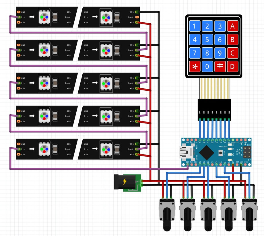
Control
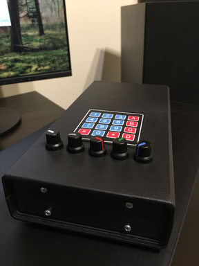
Each key on keyboard chooses one effect. Key D enables demo mode. White potentiometer changes speed of effect, gray one changes brightness, and red, green and blue one changes color component.
Connectors
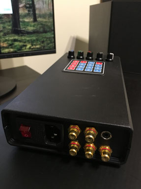
There is main power connector, 5 chinch connectors to power strings (each 5V and max 15W), a jack connector to send data.
Inside
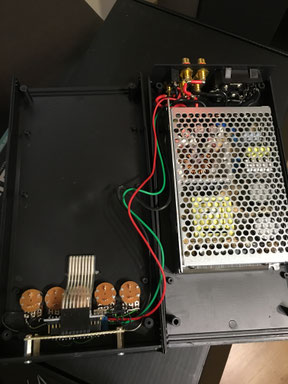
There is power supply on the bottom, and 5 potentiometers, keyboard and arduino on top.
Arduino
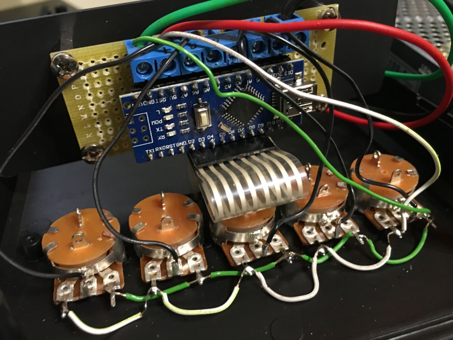
Potentiometers (10k) are connected to Arduino Nano:
Speed to A0
Brightness to A1
Red to A2
Green to A4
Blue to A6
Keyboard is connected to pins D2 to D9.
Strings are controlled by pin D13.
And last thing, source code for Arduino.
Small upgrade: when you turn off the device it will remeber the last effect, and then after turn on it will restore it.
Demo only version
Because of many requests I prepared 'demo' version which works without keyboard and potentiometers. Only arduino, power supply and diodes.
You can adjust speed, brightness, background color and diodes number to your preferences by modifying the values in the first lines of code.
And link to source code.
Write a comment
ciprian (Tuesday, 20 December 2016 17:32)
hi.. can you send me this code without keyboard and potentiometeres..only command for pin 13 to drive my led pixel tree? thanks my address [email protected]
Mark (Saturday, 21 January 2017 18:26)
Hello,i have one question.
If I upload code to the Arduino board,this board must be connected to a PC ?
Or it also works offline without connecting pc.
Thank you for your response.
Visar (Tuesday, 24 January 2017 01:38)
The Arduino needs to be connected to PC only during programming. Then it works as a standalone device, without connecting. You can disable, enable it without the connection.
Mark (Wednesday, 25 January 2017 15:27)
If I wanted to override potentiometer for changes in brightness pad brightness to 100 %
is enough to change the code of #define PBRIGHTNESS A1 to #define PBRIGHTNESS 100 ?
Thank you for your response.
Visar (Thursday, 26 January 2017 20:11)
Replace line:
int value = (analogRead(PBRIGHTNESS) >> 2) + 1;
with this one:
int value = 256;
Mark (Thursday, 26 January 2017 22:02)
Thanks for advice.
If I have only 100 led, I have to change the code of:
#define PIXEL_COUNT 250 to
#define PIXEL_COUNT 100 ?
Visar (Friday, 27 January 2017 22:22)
Yes.
Mark (Friday, 24 February 2017 17:53)
Greets you, I'd still have one request.Can you add these effects to your program?
1 - Pixie Dust
2 - Rainbow 3
5 - Rainbow 1
6 - Starry Night
Of this video https://www.youtube.com/watch?v=3Io4OeBP2GQ
If he could at least the first two effects.Or even some of your effects.Thank you very much.
Mark (Monday, 06 March 2017 12:48)
Hello, I received no response whether you look at it.
And link to source code is broken.
Visar (Friday, 10 March 2017 14:11)
Sorry, I have no time recently. I will look at it in few weeks.
Mark (Friday, 10 March 2017 23:51)
OK enough of the time, Head of Christmas is still far away.
In advance thank you very much.
Maxim (Monday, 20 March 2017 13:34)
Give please the code for arduino, the download link does not work
Mark (Wednesday, 05 April 2017 11:57)
Hi. Did you look at it now ?
1 - Pixie Dust
2 - Rainbow 3
5 - Rainbow 1
6 - Starry Night
Of this video https://www.youtube.com/watch?v=3Io4OeBP2GQ
Thank you for your response.
Maxim (Friday, 19 May 2017 15:18)
Everything was done according to your scheme. The problem with the keyboard. Only 4 keys work (1,2,3, A), only 4 effects are included. The remaining keys do not work. I checked the keyboard - all the keys are working. I checked the entire connection scheme. Potentiometers work.
Help please with the keyboard
Visar (Wednesday, 23 August 2017 15:48)
If you have still problems with keyboard, try new software. I have changed delays in keyboard procedure.
Steve R (Thursday, 14 September 2017 00:09)
hi.. can you send me this code without keyboard and potentiometeres..only command for pin 13 to drive my led pixel tree? thanks my address [email protected]
Kantesh (Wednesday, 20 September 2017 21:26)
https://youtu.be/VeGUrpI-5oQ. Need this type of code
H00GiE (Tuesday, 03 October 2017 20:22)
maybe a silly question: What would the impact be of running this on a STM32 based board be? Would the effects be (UNCONTROLABLY) faster since the STM32 is so much faster??
or would the effects be the same since (used tick based code or time based?)
I'm asking because i want to remove the keypad and potentiometers and replace it with a OLED base menu system, possible remote control as well.... and right now i'm running out of sketch storage space....
Or am i thinking too difficult and should i start using a SDcardreader for the "programs" (modes)??
Martin (Saturday, 28 October 2017 23:57)
Hello,
I want to ask for a wiring diagram. Is it that the D13 terminal is designed for the ws2811 RGB as all 5 chains are connected?
Do you write that you are individually connected to the connectors, but how exactly connected to the D13?
Thank you for answer.
Visar (Monday, 06 November 2017 11:36)
Each string has 3 wires: power, ground and data. Data wire is connected to D13 pin. Each string is connected to next string by 2 wire connector: data and ground. So, only the first one must be connected to Arduino. Each string has independent power connector. So only power is independent, data is common.
Maxim (Thursday, 09 November 2017 10:01)
Hello! Tell me please, add new effects to the firmware? New Years is soon...
Paul Andrei (Sunday, 12 November 2017 20:50)
I want to buy this project. Please
Mark (Monday, 20 November 2017 21:49)
I should have one request. You can modify the code to run the demo program when you turn it on ?
There will also be some new effects ?
Thank you for your response.
Martin (Sunday, 26 November 2017 23:18)
Could you do it and add some other program for this same device, but with new programs?
Thank you :)
Mark (Friday, 01 December 2017 18:30)
Hello Visar.
You can modify the code to run the demo program when you turn it on.
Please.
Alex (Monday, 04 December 2017 21:11)
Good evening. A code without a box is possible? Very nice project for you. I would like to work only arduino and ws2811.Thank you my mail [email protected]
JacekR. (Sunday, 10 December 2017 17:27)
Hello!
Very nice Xmans Light.
Thank You for inspiration.
I just finished my driver and now I'm going to show the effect for my wife.
Best regards!!!
ciprian (Wednesday, 20 December 2017 21:01)
hi.. can you send me this code without keyboard and potentiometeres..only command for pin 13 to drive my led pixel tree? thanks my address [email protected]
Kiran swamy (Thursday, 21 December 2017 04:59)
I want Arduino nano program for led. I don't no sir. How to program to do.led blinking, design ,as
Show your video. My emails Id is : KIRANKUMARSETTY [email protected], pl. Send mail sir .
Дмитрий (Friday, 19 January 2018 07:17)
Здравствуйте. Можно ли добавить эффект мерцающих белых огоньков по всей елке? Спасибо.
OTL (Sunday, 09 September 2018 03:36)
I just wanted to say what an awesome job....thank you!!
Inservitec (Tuesday, 25 June 2019 17:24)
Podrás poner el diagrama de conexiones
Geacias
ALEX (Friday, 20 September 2019 18:47)
Hello! You can send me this code without the keyboard and potentiometers..only work in demo mode to manage my Led pixel tree? Thanks. My address [email protected]
Ian Rebello (Wednesday, 09 October 2019 16:47)
Sir
Can you please send me the code without the pot meters and keyboard at [email protected]
Thanks in advance
Visar (Friday, 11 October 2019 21:19)
I have added source code with demo only effect. Enjoy.
Ian Rebello (Tuesday, 15 October 2019 10:00)
Sir,
Can you advise what to do to, loaded demo program , but the led connected to Pin 13 is on continuously and no output, tried with another nano , still result same , please advice , no error on uploading kindly help
Visar (Wednesday, 16 October 2019 19:02)
Hello, please send a photo of your circuit to v i s a r ( a t ) o 2 ( d o t ) p l
Ian Rebello (Saturday, 19 October 2019 08:47)
Sir,
The demo program works very nicely with 2812 ,
Ian Rebello (Saturday, 26 October 2019 03:56)
Sir,
Excellent mind blowing project, the ability to adjust colors ,intensity and speed is fantastic,l had almost given up the project as I had only changed the output pin from 13to 10 and there was no output ,as a last ditch attempt reloaded the output Pin to 13and bingo ,will be putting up my Xmas tree in Nov itself.
Can you please tell me why there is no output when changed the program from D13 to D10 for the output thanks
Visar (Sunday, 27 October 2019)
I forgot to change source code in function sending data to leds - void show().
There are two lines where the value 13 is hard coded:
const volatile uint8_t *port = portOutputRegister(digitalPinToPort(13));
uint8_t pinMask = digitalPinToBitMask(13);
You should change them to:
const volatile uint8_t *port = portOutputRegister(digitalPinToPort(PIXEL_PIN));
uint8_t pinMask = digitalPinToBitMask(PIXEL_PIN);
Ian Rebello (Monday, 28 October 2019 13:38)
Thank you Sir
Paysu (Monday, 02 December 2019 00:23)
Hi. How can I do that, in the demo version, the different modes for longer and take longer to move from one mode to another?
Thank you.
Brian (Friday, 06 December 2019 08:10)
Just want to say thanks.. this is a very classy looking sequence and makes for a very nice display.
Dhanny (Wednesday, 01 July 2020 09:09)
Hi Visar, Thank you for you amazing proyect is amazing, i have a question, if use only one button for change the modes, you have the code for this? i try modify your demo code but does not work for my. Thanks again
denis (Thursday, 22 October 2020 11:18)
i thank you very much for sharing your code it is very nice have a good day
Giovanni (Saturday, 14 November 2020 21:43)
Hi Visar, Thank you for you amazing proyect is amazing, i have a question, if use only one plug rca for 3 strings with cable 1,5mm will it work?
Thank you
Mark (Wednesday, 20 January 2021 12:25)
What are the potentiometers there? Linear or logarithmic? Would you like to add any new effects? Thank you for your response
Thank you for your response.
next_287 (Sunday, 12 November 2023 07:50)
Hello, how many LEDs can you connect maximum? Will 400 work?